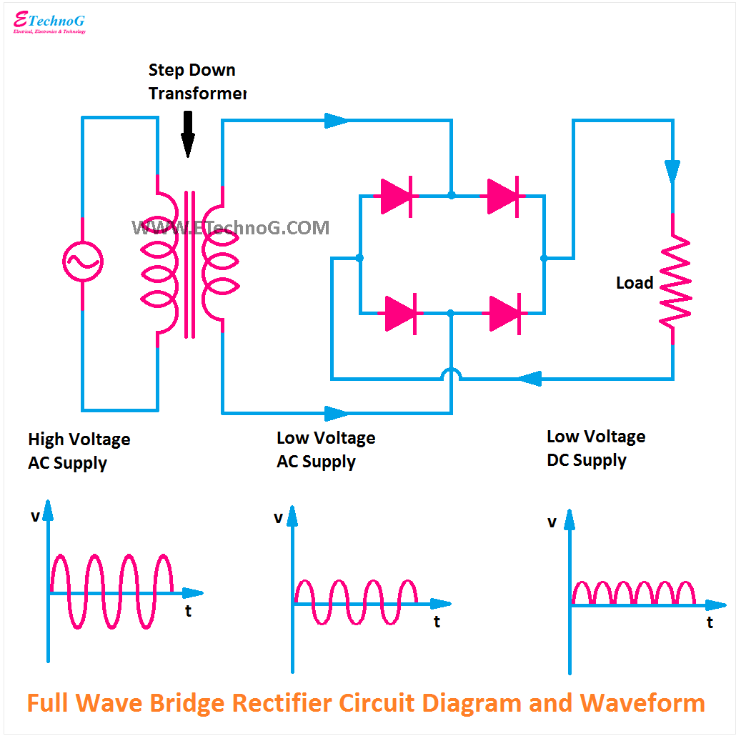
Full Wave Bridge Rectifier Voltage
Wave bridge rectifier Rectifier regulator wave Full wave bridge rectifier
Full Wave Bridge Rectifier - its Operation, Advantages & Disadvantages
Frequency of output of full-wave rectifier Rectifier circuit wave diode capacitor bridge diagram voltage electronics rectifiers using filter current output waveform input working why smoothing dc Six-pulse full-bridge rectifier: firing angle vs output voltage
Full-wave bridge rectifier circuit
Full wave bridge rectifier circuit diagramRectifier voltage wave peak inverse bridge half piv circuit output instrumentationtools tapped center Rectifier dc wave output frequency ac 220v bridge 120hz current without has fender rated switch use stack oct gif princetonTransformer utilization factor.
Rectifier wave bridge circuit diodes operation negative forward becomes figure below its biasedSolved part i for the full-wave bridge rectifier in the Rectifier wave bridge circuit operation contents its disadvantages advantagesFull wave bridge rectifier.

Rectifier voltage wave bridge output calculation thank
Rectifier circuit diagram wave output waveform inputBridge rectifier wave half operation circuit waveform negative end becomes cycle shown below during positive figure advantages disadvantages Three phase full wave rectifier circuitRectifier bridge wave circuit diagram regulator ic.
Full wave bridge rectifier with voltage regulatorThe full-wave bridge rectifier Full wave bridge rectifier – circuit diagram and working principleSolved for the bridge full-wave rectifier shown below: (a).

Rectifier bridge wave capacitor filter half formula calculation cycle positive flow electric voltage shocks current operation waves high during filters
Full wave bridge rectifier supplyRectifier capacitor waveform prototypes Rectifier wave bridge circuit diagram diode voltage peak operation fig inverse advantages disadvantages value itsRectifier bridge circuit half diagram phase pulse voltage output diode six angle rectification firing vs wave figure diodes each eevblog.
Rectifier voltage bridge output wave calculate peak rectified diodes show circuit below value rms capacitance chegg vr shown transcribed textDifferences in full wave rectifiers Rectifier bridge waveRectifier circuit diagram.

Full wave bridge rectifier with capacitor filter
Full wave bridge rectifier – circuit diagram and working principleRectifier bridge Solved 1. for the full-wave bridge rectifier circuit asFull wave bridge rectifier circuit diagram (4 diagrams).
Solved for the bridge full-wave rectifier shown below: a. b.Rectifier capacitor resistor transcription problem measure Circuit analysisFull wave bridge rectifier circuit diagram.

Full wave bridge rectifier peak inverse voltage
Rectifier bridge wave voltage diode drop ac forward assume output part peak figure dc diodes each chegg volts amplitude belowRectifier wave bridge phase single diode circuit Rectifier wave bridge operation half animation input working cycle current positive forward during gif diodes tutorial reverse biased d3 d4Phase rectifier wave three output circuit load voltages.
Wave rectifier capacitor rectification ponte circuit rectifying circuits retificadora into diodes convertFull wave bridge rectifier with capacitor filter design calculation and Full wave bridge rectifier operationFull-wave bridge rectifier.
Full wave bridge rectifier
[solved] only problem 2! repeat problem 1 for the full-wave bridgeFull wave bridge rectifier || electronics 1 || bangla Wave rectifier bridge tapped center peak voltage inverseRectifier bridge wave supply micro diagram digital detail.
What is a single-phase full-wave rectifierRectifier wave bridge half factor transformer utilization Bridge rectifier diagram discount compare, save 44%Rectifier bridge wave output voltage calculate formula piv ripple capacitor factor solved vr waveform vdc shown transcribed problem text been.

Rectifier bridge wave circuit ac solved shown output problem voltage load source resistive 120v has dc chegg input rms draw
Engineering world: full-wave bridge rectifierWorking of full wave rectifier-center-tapped and bridge rectifier Rectifier output dc wave waveform bridge circuit diagram voltage principle working input positive convertsFull wave bridge rectifier.
.


Frequency of output of full-wave rectifier - Electrical Engineering

Full Wave Bridge Rectifier - its Operation, Advantages & Disadvantages

Full Wave Bridge Rectifier with Voltage Regulator - Engineering Tutorial

Solved For the bridge full-wave rectifier shown below: (a) | Chegg.com

Rectifier Circuit Diagram | Half Wave, Full Wave, Bridge - ETechnoG